
Understanding Top-End Ticks in Harley-Davidson Twin Cam, EVO, and Sportster Engines
Top-end ticking noises are a common concern for owners of Harley-Davidson Twin Cam, EVO, and Sportster engines. While these motors share a similar rocker arm, shaft, and rocker arm plate design, several factors can contribute to these audible issues.
Primary Cause: Rocker Arm Shaft Rotation
The most significant source of top-end noise is often the rocker arm shaft rotating and making contact with its retaining bolt. This occurs due to an inherent gap between the bolt and the shaft. Fortunately, this common problem can be effectively resolved with the installation of “Rocker Lockers,” which eliminate this excessive clearance.
Secondary Cause: Excessive Rocker Arm End Play
Another contributing factor to top-end noise is excessive end play of the rocker arm between its towers. While the factory specification for this clearance is between 0.003 and 0.013 inches, it’s common to observe measurements of 0.015 inches (cold).
Furthermore, the difference in the coefficient of thermal expansion between the steel rocker arm and aluminum rocker box components exacerbates this issue. As the engine heats from 32°F to 350°F, this gap can expand by approximately 0.004 inches, leading to clearances as wide as 0.019 inches. This increased clearance allows for more movement and potential noise.
Evolution of Understanding: Why Shimming Lost Favor
Historically, shimming the rocker arm end play was a common practice. However, its effectiveness declined as the primary cause of ticking – the rocker arm shaft hitting the bolt – was not widely understood.
It’s also worth noting the design differences between the EVO and Twin Cam engines. The single-cam EVO engine introduced a greater angle on the pushrods, which, in turn, applied additional side loads to the rocker arms. This design inherently increased the EVO’s tendency for the rocker arms to slap against the towers. In contrast, the Twin Cam engine’s more perpendicular pushrod orientation significantly reduces the propensity for rocker arm side play.
This end play tick can still be a factor in SOME bikes.
If you have seen the video of the end play cutter.
Updated End Play Adjustment Method
This video demonstrates an earlier, experimental method for adjusting rocker arm end play using a specialized cutter. Since then, we have refined our process and now recommend a more effective approach utilizing a stationary sanding station. This updated method involves removing excess material directly from the rocker arm itself, rather than altering the rocker arm towers. Despite this change in technique, the measurement specifications and desired fitment remain consistent with those shown in the video.
Pre-Disassembly End Play Check
Before disassembling the rocker arm assembly, it is crucial to check the existing end play using a feeler gauge. Perform this measurement on the non-load side at the bottom of the rocker arm, as this is typically where the clearance is at its tightest.
From Zippers, on a twin cam non load is, left side on intake, right side on exhaust), this is the side where the cutting is done and the shims are installed.
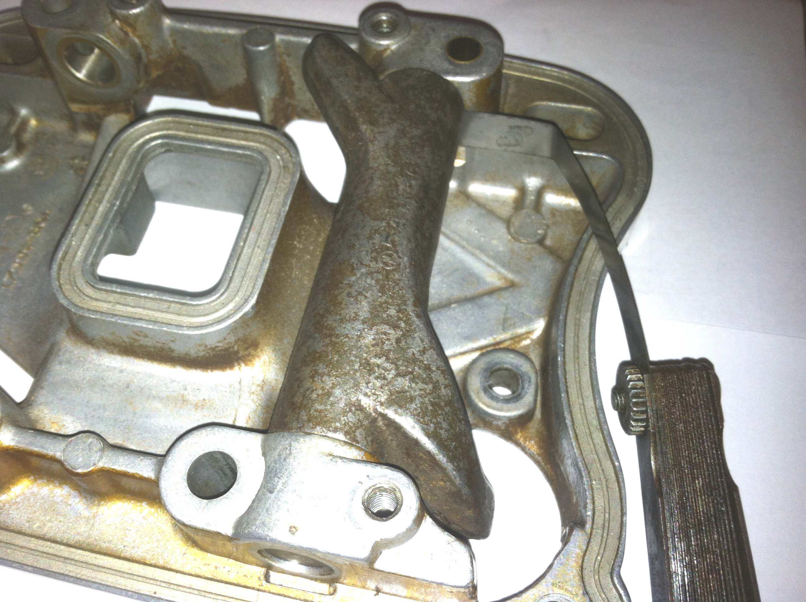
If you look at the push rods on a twin cam motor you can see that it has two cams, also that the lifters are side by side on that cam.
Understanding Rocker Arm Alignment and End Play
Due to the inline design of the rocker arms within the assembly, the pushrods are set at an angle. This angle creates a side load on the rocker arms. Specifically, the rear (exhaust) pushrod leans inward, pushing its rocker arm inward, while the intake pushrod leans outward, pushing its rocker arm outward.
Because of these forces, you should always check the end play on the non-thrust side, which is where the gap exists. This also dictates the correct placement for any shims. Shims should never be placed on the thrust or wear side, as their purpose is to set clearance, not to act as a bearing surface.
Critical Measurement Techniques
It’s crucial to measure rocker arm end play at the bottom of the rocker arm, not the top. In every rocker arm I’ve inspected, the clearance was tighter at the bottom, or the arm itself was slightly longer on both ends at the bottom.
When disassembling, it’s vital to mark the rocker arm plate for front and rear orientation. Once shims are installed, they must be returned to the same head. Furthermore, marking the plate is essential because the shim location differs between the front and rear heads due to the changing load side of the rocker arm.
Thermal Expansion and Target Clearances
Keep in mind the coefficient of thermal expansion between the aluminum rocker box components and the steel rocker arm. Aluminum expands more than steel, meaning the end play actually increases with heat. Conversely, placing the assembly in a freezer will cause the gap to shrink. This thermal behavior is why we target a minimum cold clearance of 0.003 inches for proper cold starts.
Adjusting Rocker Arm Length
If your rocker arm shaft has Rocker Lockers installed, you can easily remove them by gently tapping them out from the bottom with a punch.
Shimming Best Practices
Most experts recommend against the use of thin shims (typically under 0.015-0.020 inches) because they are prone to disintegrating and falling into the engine. If you are confident that thin shims won’t be an issue, then adjusting the rocker arm gap might not be necessary. We want to use shims designed for EVO engines when performing this procedure.
Precision Grinding for Optimal Fit
When removing material, consider which side of the rocker arm you want to shorten. Check the alignment of the rocker arm foot on the valve stem to decide if moving the arm to one side or the other would optimize its position. Ideally, the rocker arm should contact the valve stem slightly off-center, allowing for a rolling motion during valve lift, this will cause the valve to turn while lifting, ensuring even wear and optimal performance.
Measure the rocker arm and subtract the determined removal amount to establish your new target length. Periodically re-measure as you grind to track your progress.
When using a sanding station, avoid overly coarse sandpaper initially. Your goal is to sneak up on the final fit. Once you’re within 0.002 inches of your target length, stop and check the clearance with the rocker arm and shaft installed using a feeler gauge. Use finer grit paper to remove the last few thousandths. It’s always better to err on the side of a slightly loose fit than one that’s too tight. I recommend starting with 220-grit paper and finishing with 330-grit, frequently checking your work to gauge your cutting speed.
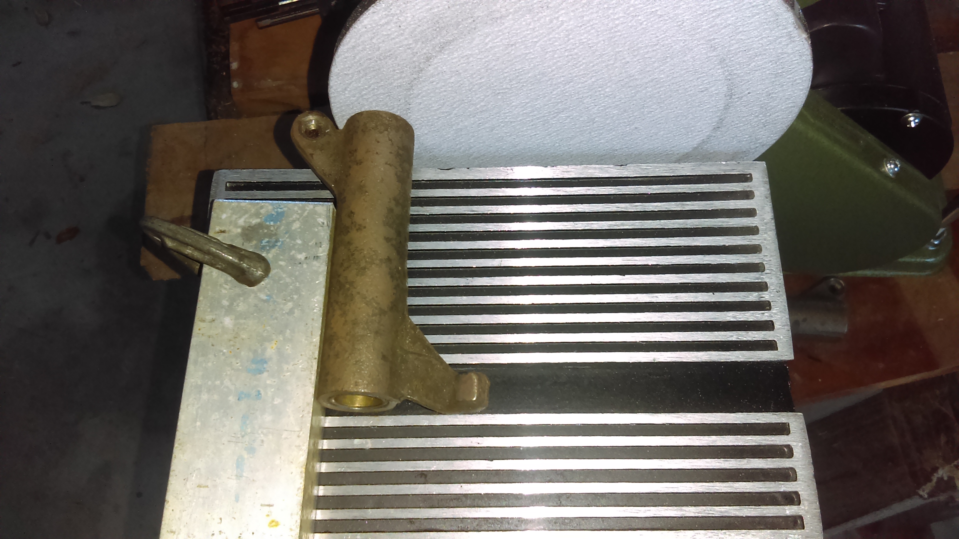
Sanding Station Setup
On the sanding station, it’s crucial to align your shaft carefully to ensure material is removed evenly. Use the factory edge of the rocker arm as a guide. Based on my observations, the factory edge is not perfectly perpendicular to the shaft; it tends to be slightly longer on the bottom on all shafts I’ve checked.
To achieve the correct angle for grinding, I adjust the table and then use a scrap piece of aluminum to precisely align the shaft.
Post-Grinding Cleanup and Assembly
After cutting, ensure all parts are thoroughly cleaned and well-lubricated. Don’t hesitate to wash them with soap and water in a sink. Lubricating before installing your Rocker Lockers and mounting the assembly on the bike is crucial. Once installed on the bike, recheck the end play to confirm that torquing the rocker arm plate did not alter the measured gap.
Addressing Pushrod Tube Rubbing
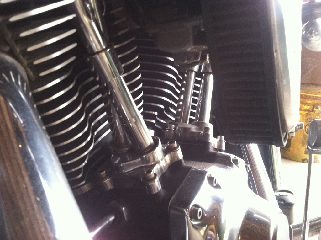
The final area to inspect for potential noise is whether the pushrods are rubbing against their tubes, a common issue, especially with thicker adjustable pushrods.
You can often detect rubbing by gently grasping the pushrod tubes and moving them to feel for resistance. Another method is to look down the tubes from the top and use a thin, flexible object, such as a straw cut lengthwise, as a feeler gauge to check for adequate clearance.
In most cases, the installation of Rocker Lockers effectively centers the rocker arm plate, significantly reducing or eliminating issues with pushrod tube rubbing.
However, there have been instances where the lower rocker housing was not properly centered on the cylinder head, leading to pushrod rubbing. When installing this housing, it must be centered on the head. If rubbing is observed, realignment may be necessary. Some users have found it helpful to temporarily use the Rocker Lockers as a guide on the bolts to help center the housing before removing them and fully torquing it down.
For final assembly and torque specifications, always consult your service manual.
Please Share on Facebook